X
Our staff will contact you within 12 hours, You can also contact us through the following ways:
Contact US WhatsApp: +8618766656705
- Email: [email protected]
- Tel: +8618766656705
- Web: https://www.toponechain.com/


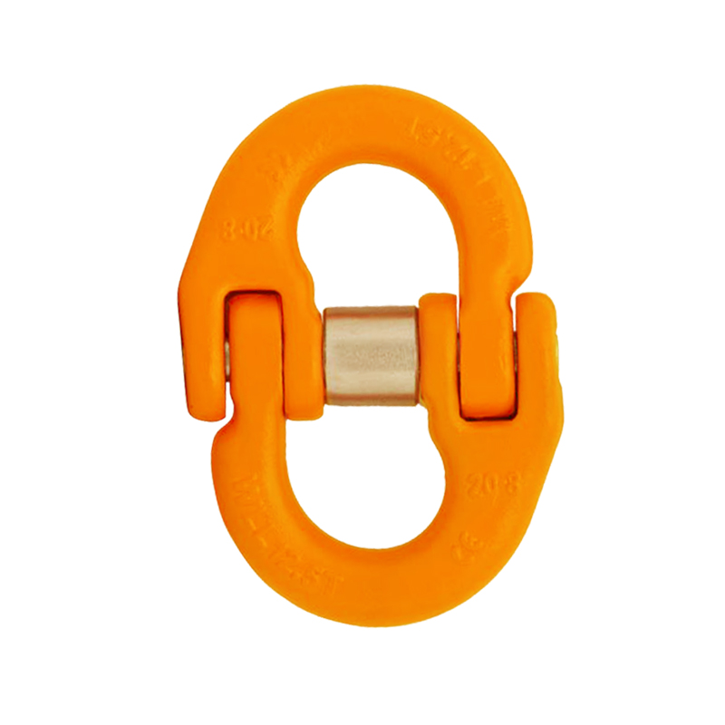


Grade 100 Connecting LinkQuenched and Tempered Alloy Steel.At least 25% greater WLL than traditional G80 products.Manufactured in accordance with EN 1677- 1 and ASTM A952/ A952M, DIN PAS 1061.Proof Load tested at 2.5 times the WLL with certification for each batch manufactured.Design Factor 4:1.Fatigue rated to 20,000 cycles at 1.5 times the WLL.Suitable for use with both Grade 80 and Grade 100 chain.
Understanding the Grade 100 Connecting Link
The Role of Connecting Links in Chain Sling Assembly
The connecting link is one of the most critical components in professional chain sling assemblies. While often overlooked, the connecting link is responsible for securely joining the chain leg to the master link at the top of the sling and to the hook or shackle at the bottom. This dual connection point makes the connecting link a critical safety component that must be engineered for maximum reliability.
The Grade 100 connecting link represents the pinnacle of connecting link technology, offering superior strength, reliability, and performance compared to lower-grade alternatives.
Why Grade 100 Matters
The Grade 100 designation refers to the minimum breaking load of the steel material, which is 100 ksi (kilopounds per square inch) or approximately 690 MPa. This higher material strength provides several critical advantages [1]:
1 Higher Capacity: Grade 100 material allows for higher working load limits in the same size connector [1].
2 Compact Design: The higher strength allows for more compact connectors that fit into tighter spaces while handling heavier loads [2].
3 Longer Service Life: The superior material properties provide better fatigue resistance and longer service life [1].
4 Better Performance Under Dynamic Loading: The higher strength provides better performance under shock loads and dynamic loading conditions [2].
5 Proven Reliability: Grade 100 has been the industry standard for professional lifting applications for decades [1].
The Engineering Behind Grade 100 Connecting Links
Material Composition and Properties
The Grade 100 connecting link is manufactured from premium quenched and tempered alloy steel with the following typical composition [1] [2]:
Element | Typical Content | Purpose |
Carbon (C) | 0.35-0.45% | Primary hardening element |
Manganese (Mn) | 0.6-0.9% | Improves strength and hardenability |
Chromium (Cr) | 0.5-0.8% | Improves hardness and corrosion resistance |
Molybdenum (Mo) | 0.15-0.25% | Improves strength and toughness |
Silicon (Si) | 0.15-0.35% | Improves strength and elasticity |
Nickel (Ni) | 0.3-0.6% | Improves toughness and ductility |
Material Properties [1] [2]:
Property | Specification | Significance |
Tensile Strength | ≥1,800 MPa | Provides high strength in relatively small size |
Yield Strength | ≥1,600 MPa | Ensures elastic behavior under normal loads |
Hardness | 45-50 HRC | Provides wear resistance and durability |
Elongation at Break | 8-12% | Provides controlled ductility for safety |
Impact Resistance | >50 J | Provides safety under shock loads |
Heat Treatment Process
The Grade 100 connecting link undergoes a precise three-step heat treatment process to achieve its optimal mechanical properties [1] [2]:
6 Austenitization (850-900°C): The steel is heated to dissolve all carbides and achieve a uniform austenitic structure.
7 Quenching (Oil Quench): The steel is rapidly cooled in oil to create a hard martensitic structure.
8 Tempering (400-500°C): The steel is reheated to a controlled temperature to relieve internal stresses and achieve the optimal balance of hardness and toughness.
This heat treatment process creates a material with exceptional strength, toughness, and fatigue resistance.
Mechanical Assembly Design
The Grade 100 connecting link consists of two symmetrical forged halves with the following design features [3]:
9 Symmetrical Halves: The two halves are identical, allowing for balanced load distribution.
10 Structural Load Pin: A hardened steel pin passes through both halves, transferring the load.
11 Retaining Spring: A spring-loaded sleeve retains the load pin and prevents accidental disassembly.
12 Optimized Geometry: The internal geometry is optimized to distribute stress evenly and minimize stress concentration.
This design allows for:
• Quick on-site assembly without special tools.
• Secure connection that cannot accidentally disassemble.
• Easy disassembly if needed for maintenance or reconfiguration.
• Balanced load distribution under all loading conditions.
Manufacturing Excellence
Forging Process
Each connecting link is precision-forged from a single piece of steel, ensuring a dense, strong material with optimized grain structure [1] [2]:
13 Blank Preparation: A steel blank is heated to forging temperature (1,100-1,200°C).
14 Primary Forging: The blank is forged into approximate shape using industrial forging presses.
15 Secondary Forging: The forging is refined to achieve precise dimensions and grain structure.
16 Cooling: The forging is cooled in a controlled manner to prevent cracking.
17 Trimming: Excess material is trimmed to achieve final dimensions.
The forging process creates a dense, strong material with optimized grain structure that is superior to cast or machined alternatives.
Heat Treatment
After forging, each connecting link undergoes the precise heat treatment process described above.
Machining and Finishing
After heat treatment, each connecting link undergoes precision machining to achieve exact dimensions [1]:
18 Boring: The internal bores are machined to precise dimensions.
19 Grinding: Critical surfaces are ground to achieve precise dimensions and smooth finish.
20 Deburring: All sharp edges are removed.
21 Inspection: Dimensions are verified to ensure compliance with specifications.
Quality Control
Every connecting link undergoes rigorous quality control [1] [2]:
22 100% Magnaflux Inspection: Every connecting link is inspected using Magnaflux crack detection to identify any internal defects.
23 Proof Testing: Sample connecting links are proof tested at 2.5 times working load limit.
24 Load Pin Testing: Every load pin is individually inspected and tested.
25 Dimensional Verification: All dimensions are verified to be within specification.
26 Surface Inspection: The surface is inspected for defects or damage.
Powder Coating
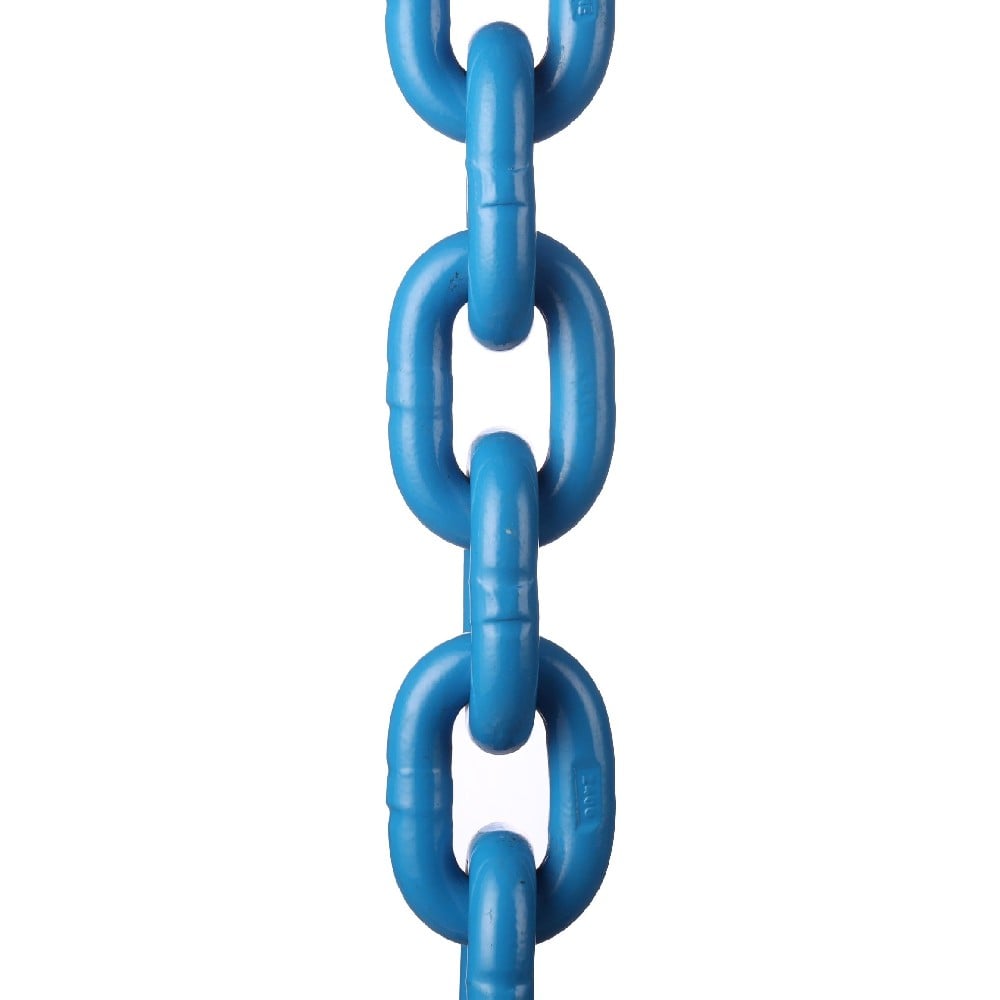
After quality control, each connecting link is finished with durable blue powder coating [3]:
27 Surface Preparation: The surface is cleaned and prepared.
28 Powder Application: Blue powder is electrostatically applied.
29 Curing: The powder is cured in an oven to create a durable finish.
30 Final Inspection: The finish is inspected for uniformity and coverage.
The blue powder coating provides:
• Corrosion protection for extended service life.
• Easy visual identification of Grade 100 components.
• Professional appearance.
• Durable finish that resists chipping and scratching.
Performance Characteristics
Working Load Limit (WLL) Range
The Grade 100 connecting link is available in various sizes with working load limits ranging from 1.4 tons to 40 tons [1] [2]:
Chain Size (mm) | WLL (tons) | Typical Applications |
6mm | 1.4 | Small lifting, laboratory equipment |
8mm | 2.5 | Light industrial lifting |
10mm | 4 | General purpose lifting |
13mm | 6.7 | Medium industrial lifting |
16mm | 10 | Heavy industrial lifting |
20mm | 16 | Very heavy industrial lifting |
22mm | 19 | Very heavy industrial lifting |
26mm | 26.5 | Extreme heavy lifting |
32mm | 40 | Maximum capacity lifting |
Safety Factor
The Grade 100 connecting link is designed with a 4:1 safety factor, meaning [1]:
WLL = Minimum Breaking Load ÷ 4
For example, for a 16mm connecting link with a Minimum Breaking Load of 40 tons:
• Working Load Limit: 40 ÷ 4 = 10 tons
This 4:1 safety factor accounts for:
• Material variability.
• Environmental degradation.
• Fatigue from repeated loading.
• Shock loads and dynamic effects.
• Wear and corrosion over time.
Proof Testing
Every connecting link is proof tested at 2.5 times working load limit [1]:
Proof Load = WLL × 2.5
For the 16mm connecting link:
• Working Load Limit: 10 tons
• Proof Load: 10 × 2.5 = 25 tons
This proof testing ensures that every connecting link can safely handle occasional overloads up to 2.5 times the working load limit without permanent deformation.
100 ChainParameter

Working Load Limit For Grade
inchDimensions (inch) Weight
(lbs)lbs. tons A B D K 5,700 2.5 1/4-5/16 0.71 0.98 0.35 2.32 0.4 8,800 4.0 3/8 0.98 1.10 0.43 2.72 0.7 15,000 6.7 1/2 1.18 1.50 0.63 3.62 1.5 22,600 10.0 5/8 1.42 1.61 0.75 3.98 2.6 35,300 16.0 3/4 1.65 1.97 0.91 4.80 4.6 42,700 19.0 7/8 1.93 2.48 0.95 5.98 7.7
International Standards Compliance
EN 1677-1: Safety Requirements for Lifting Chains, Components and Attachments [1]
EN 1677-1 is the primary European standard governing lifting chains and components, including connecting links:
Material Requirements:
• Grade 100 material must have minimum tensile strength of 1,800 MPa.
• Material composition must meet specified ranges for carbon, manganese, chromium, molybdenum, and other elements.
• Material must be tested to verify chemical composition.
Manufacturing Requirements:
• Connecting links must be forged from solid steel (not cast).
• Heat treatment must be applied to achieve specified hardness (45-50 HRC).
• Dimensions must be within specified tolerances.
• Surface finish must be uniform and free of defects.
Testing Requirements:
• Every connecting link must be proof tested at 2.5 times working load limit.
• Sample connecting links must be fatigue tested at 1.5 times working load limit for 20,000 cycles.
• 100% Magnaflux crack detection must be performed on every connecting link.
• Load pins must be individually inspected and tested.
Performance Specifications:
• Minimum breaking loads must be met for each size.
• Safety factor must be 4:1 (WLL = Breaking Load ÷ 4).
• Fatigue rating must be 1.5 × WLL for 20,000 cycles.
The Grade 100 connecting link fully complies with all EN 1677-1 requirements.
ASTM A952: Standard Specification for Grade 100 Alloy Steel Lifting Components [2]
ASTM A952 is the American standard for Grade 100 alloy steel lifting components:
Material Requirements:
• Minimum tensile strength: 1,800 MPa (260 ksi).
• Minimum yield strength: 1,600 MPa (230 ksi).
• Hardness: 45-50 HRC.
• Material composition within specified ranges.
Manufacturing Requirements:
• Components must be forged from solid steel.
• Heat treatment must be applied to achieve specified properties.
• Dimensions must be within specified tolerances.
• Surface finish must be uniform.
Testing Requirements:
• Proof testing at 2.5 times working load limit.
• Fatigue testing at 1.5 times working load limit for 20,000 cycles.
• 100% Magnaflux crack detection.
• Individual load pin testing.
The Grade 100 connecting link fully complies with all ASTM A952 requirements.
Regulatory Compliance
International Maritime Organization (IMO) Requirements
For maritime lifting applications, the Grade 100 connecting link complies with [5]:
• SOLAS (Safety of Life at Sea) requirements.
• ISM Code (International Safety Management Code).
• Port state control requirements.
Classification Society Requirements
The Grade 100 connecting link meets the requirements of major classification societies [5]:
• DNV GL (Det Norske Veritas - Germanischer Lloyd).
• Lloyd's Register.
• ABS (American Bureau of Shipping).
• ClassNK (Nippon Kaiji Kyokai).
• CCS (China Classification Society).
OSHA Requirements (United States)
For workplace lifting applications, the Grade 100 connecting link complies with [6]:
• OSHA 1910.184 (Slings and Rigging Hardware).
• ANSI B30.20 (Below-the-Hook Lifting Devices).
CSA Requirements (Canada)
For Canadian applications, the Grade 100 connecting link complies with [7]:
• CSA B335 (Safety Code for Rigging).
• CSA B149 (Lifting and Hoisting Equipment).
Testing and Certification
Proof Testing [1]
Every connecting link is proof tested at 2.5 times working load limit:
• Test Method: The connecting link is subjected to a load of 2.5 × WLL for a specified duration.
• Sample Selection: All connecting links are tested (100% testing).
• Test Equipment: Calibrated testing machines with load cells accurate to ±1%.
• Test Report: Detailed reports document the test results.
• Acceptance Criteria: Connecting links must show no permanent deformation.
Fatigue Testing [1]
Sample connecting links are fatigue tested to verify fatigue rating:
• Test Method: The connecting link is subjected to repeated loading at 1.5 × WLL for 20,000 cycles.
• Sample Selection: Sample connecting links are randomly selected from each production batch.
• Test Equipment: Hydraulic testing machines with automated cycle counting.
• Test Report: Detailed reports document the fatigue test results.
• Acceptance Criteria: Connecting links must show no cracks or permanent deformation.
Magnaflux Crack Detection [1] [2]
Every connecting link undergoes 100% Magnaflux crack detection:
• Test Method: The connecting link is magnetized and inspected for internal defects.
• Sample Selection: All connecting links are inspected (100% inspection).
• Test Equipment: Calibrated Magnaflux equipment with certified operators.
• Test Report: Detailed reports document any defects found.
• Acceptance Criteria: No cracks or defects are acceptable.
Load Pin Testing [1]
Every load pin is individually inspected and tested:
• Visual Inspection: Each pin is visually inspected for defects.
• Dimensional Verification: Pin diameter is verified to specification.
• Hardness Testing: Pin hardness is verified to be within specification.
• Test Report: Detailed reports document all test results.
Certification [1] [2]
Each Grade 100 connecting link is supplied with:
• Test certificate documenting proof testing results.
• Material certificate documenting chemical composition.
• Magnaflux inspection report.
• Dimensional verification report.
Maintenance and Inspection Guidelines
Regular Inspection Procedures [8]
Connecting links should be inspected regularly to detect signs of damage or degradation:
Visual Inspection:
• Check for visible cracks or breaks in the material.
• Look for signs of permanent deformation or bending.
• Verify that the blue powder coating is intact.
• Check that the load pin is secure and not loose.
• Verify that the retaining spring is present and functional.
Physical Inspection:
• Feel the connecting link for rough spots or damage.
• Check that the load pin moves freely but is not loose.
•