A marine fender system must absorb berthing energy while limiting loads on the vessel and berth. It serves ports, terminals, shipyards and offshore facilities.
Design Basis
Energy, Reaction and Hull Pressure
The kinetic starting point is E = 0.5 × M × V², but M and V are not deadweight and service speed. Design uses vessel displacement and normal berthing velocity with added-mass, eccentricity and applicable factors. Approach angle, berth geometry, water level and multiple fender contact also require assessment.
Energy absorption must equal or exceed required berthing energy. Reaction must remain within berth and anchorage capacity, and hull pressure within the vessel limit. Energy capacity alone is insufficient if reaction or contact pressure is excessive.
System Load Path
Load passes from the hull through low-friction facing and a steel panel, into the rubber element and berth. Rubber is the principal energy absorber. The panel spreads reaction, and the facing reduces sliding friction. Chains support or control the assembly; they are not the primary energy absorber.
Application Matching
Fixed Berths and Shipyards
Panel systems are used where high energy absorption and controlled hull pressure are required. Cylindrical or arch systems may suit other conditions. Type, panel size, elevation and spacing must cover the vessel range, tide and bow contact geometry. Vessel tonnage alone cannot select a fender.
Offshore and Floating Facilities
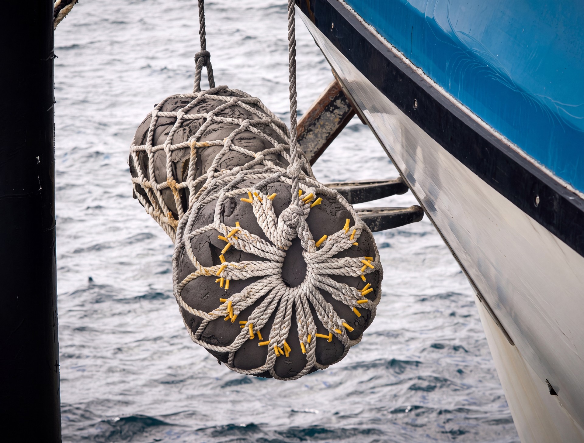
Floating pneumatic or foam-filled fenders can follow water-level changes and be relocated for ship-to-ship or ship-to-structure service. ISO 17357-1 applies to high-pressure floating pneumatic rubber fenders. Quantity, stand-off, fittings and mooring loads remain project-specific.
Chain and Connection Engineering
Support, Tension and Shear Chains
Support chains carry panel dead weight and maintain elevation. Tension and shear chains, where fitted, control panel movement and protect the rubber unit from unintended tensile or excessive shear load. Design considers panel mass, chain angle, friction, impact direction, travel, dynamic effects and load sharing. Length, slack or pretension and attachment geometry require calculation; no vessel class has a universal chain diameter.
TOPONE Component Range
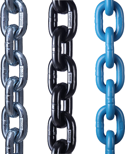
The TOPONE catalogue lists stud-link and studless marine anchor chains from 6–107 mm, swivels from 6–107 mm, joining and end shackles from 13–65 mm, and non-standard anchor-chain components from 13–70 mm. These are manufacturing ranges, not fender-chain ratings.
Components must match calculated loads, proof and minimum breaking loads, connector geometry, corrosion allowance, coating and certification. Anchor-chain catalogue loads cannot be assigned directly to a fender system without verification.
Materials and Quality Control
Rubber, Steel and Chain
Rubber performance depends on compound, production, vulcanisation, temperature and compression velocity. Energy-absorption and reaction curves need project testing; hardness alone is insufficient. Steel panels require structural verification, controlled welding and marine corrosion protection. Facing and fasteners must suit hull pressure and wear.
Chain orders should define material grade, dimensions, heat treatment where applicable, proof and breaking tests, coating, marking and traceability. Chain, shackles, brackets and berth anchors form one load path; an undersized connector or fixing controls capacity.
Inspection and Selection Data
Inspection
Check rubber for cracking, abrasion, separation and permanent deformation. Inspect panel distortion, corrosion, facing, fasteners, brackets and anchors. Measure chain and shackle diameter loss, elongation and wear; check twisted links, weld areas, pins and locking devices. Apply specified replacement limits.
Information Required
Provide vessel displacement, hull geometry, normal approach velocity and berthing procedure; berth type, elevation, tide and anchor layout; required energy, allowable reaction and hull pressure; panel mass and travel; chain load cases, connections, corrosion system, standards and certificates.
PIANC Report 211:2024 covers fender design, manufacturing and testing. BS 6349-4:2026 covers fendering and mooring design principally for commercial vessels of at least 1,000 t displacement. ISO 17357-1:2014 remains current for high-pressure floating pneumatic rubber fenders. Final sizing follows project calculations and approval requirements.