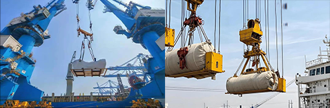
Break bulk cargo transported through a RoRo terminal may include construction machinery, industrial equipment, transformers, wind turbine components, railway vehicles, boats, steel structures, refinery modules, and other cargo that cannot travel onto the vessel independently.
In this application, the cargo is normally placed on a rolltrailer and moved through the terminal by a terminal tractor fitted with a detachable gooseneck. The rolltrailer converts a static or non-self-propelled cargo unit into a mobile unit that can be transferred horizontally across the vessel ramp.
Typical applications include:
Industrial machinery shipment
Wind turbine component transport
Transformer and generator shipment
Railway equipment logistics
Boat and marine equipment transport
Construction machinery shipment
Steel structure and project cargo transport
Refinery and offshore module shipment
The dimensions, mass, support footprint, centre of gravity, structural strength, and attachment points of break bulk cargo can vary substantially. Rolltrailers are consequently available in different lengths, deck arrangements, wheel configurations, payload classes, and support structures. Extremely long, heavy, or concentrated cargo may require a specially selected or engineered rolltrailer.
A break bulk cargo securing system involves two independent load paths.
The cargo must first be secured to the rolltrailer.
The loaded rolltrailer must then be secured to the vessel’s deck.
Neither stage can compensate for a weakness in the other. A properly secured rolltrailer can still be unsafe if the machinery moves on its platform, while properly restrained machinery remains unsafe if the complete rolltrailer is inadequately connected to the deck.
How the Two-Stage Securing System Works
Stage One: Cargo to Rolltrailer
The first system prevents the machinery, structure, or project cargo from sliding, tipping, rotating, rolling, or separating from the rolltrailer.
This system may combine direct chain lashings, heavy web lashings, steel wire-rope lashings, support frames, timber dunnage, rubber friction material, chocks, stoppers, cradles, cargo nets, and edge protection.
The cargo-to-rolltrailer calculation must be based on the actual cargo mass rather than the combined mass of the cargo and trailer. It must also consider the cargo centre of gravity, support width, lashing-point position, rolltrailer anchor ratings, and the strength of the cargo attachment points.
The cargo should preferably have designated securing points that transfer lashing forces into its structural frame. Handrails, thin covers, hydraulic pipes, ladders, cable trays, exhaust systems, lifting lugs with unknown side-load capacity, and unverified fabrication details must not be used as convenient lashing points.
When designated points are unavailable, a qualified engineer must establish suitable structural connections or develop a loop-lashing, cradle, blocking, or fabricated attachment arrangement.

Stage Two: Rolltrailer to Vessel Deck
The second system prevents movement of the complete rolltrailer and cargo combination relative to the vessel.
The mass used at this stage includes the cargo, rolltrailer, permanent support structures, dunnage, and any other equipment travelling as part of the unit.
Chain lashings or approved heavy web lashings are connected between dedicated rolltrailer securing points and the vessel’s deck eyes or sockets. Their arrangement must control transverse sliding, longitudinal sliding, vertical movement, and overturning.
The terminal tractor and detachable gooseneck are used to position the rolltrailer. After the tractor is disconnected, the coupling system must not be assumed to provide voyage restraint.
The quantity, direction, and MSL of the lashings must comply with the vessel’s approved Cargo Securing Manual. General product strength alone cannot establish the correct number of lashings.

Why the Two Systems Must Be Calculated Separately
The cargo-to-rolltrailer system and rolltrailer-to-deck system may have different masses, attachment geometry, friction conditions, and structural limitations.
For example, a 35-tonne machine placed on a 10-tonne rolltrailer creates two calculation masses:
Cargo-to-rolltrailer calculation mass 35 tonnes
Rolltrailer-to-deck calculation mass 45 tonnes
Using 35 tonnes for the deck-securing calculation would omit the rolltrailer’s mass. Using 45 tonnes for the machinery lashing calculation could incorrectly assume that the trailer’s mass increases the stability of machinery that is free to move on its deck.
Each load path must therefore be demonstrated independently.
Selecting the Rolltrailer and Support Arrangement
Payload Is Not the Only Selection Parameter
The marked payload of the rolltrailer is the starting point rather than the complete selection criterion.
The following conditions must also be confirmed:
Permissible concentrated deck load
Rolltrailer tare mass
Cargo support footprint
Longitudinal centre-of-gravity position
Transverse centre-of-gravity position
Deck height and ramp clearance
Available securing-point locations
Securing-point MSL
Wheel and axle reactions
Gooseneck compatibility
Jack and support locations
Overall cargo height, width, and length
A rolltrailer with sufficient total payload can still be unsuitable when a transformer or machine base applies its weight through several narrow feet.
Steel beams, timber beams, grillages, stools, or load-spreading frames may be required to distribute the load into the rolltrailer’s main structure.
Cargo Support and Load Distribution
Cargo should be supported at structurally suitable locations. Support points must not damage machinery frames, pressure vessels, tanks, bearings, shafts, pipe connections, or thin fabrication.
The support arrangement must remain stable while the cargo is being loaded, transported through the terminal, transferred across the ramp, and carried at sea.
Timber used as structural dunnage should be selected for the load direction, bearing pressure, bending load, moisture condition, grain direction, and possible splitting. Random pieces of soft timber should not be assigned an assumed capacity.
Fabricated steel grillages require documented material, weld details, contact areas, structural calculations, and connection arrangements.
The support system should provide access for lifting slings or jacks without requiring personnel to place hands or feet beneath unsupported cargo.
High-Centre-of-Gravity Cargo
Transformers, boats, machinery housings, pressure vessels, and fabricated modules may have a high centre of gravity relative to their support width.
A low rolltrailer deck can reduce the overall centre-of-gravity height, but it does not remove the overturning risk. The securing calculation must compare the overturning moment generated by transverse acceleration with the restoring moment from the unit’s weight, support width, and lashing geometry.
Lashings attached close to the bottom of a high cargo unit may provide sliding restraint while contributing little resistance to tipping. Additional higher attachment points may be necessary when the cargo structure is capable of accepting them.
The rolltrailer, deck route, ramp angle, vessel stowage position, and clear height must all be checked before loading.
Extremely Long Cargo
Wind turbine blades, rail vehicles, long steel structures, and marine components can extend beyond a standard rolltrailer.
Long cargo may require several support stools or a purpose-made trailer arrangement. The support system must account for cargo bending, deflection, torsion, overhang, and changes in load distribution as the rolltrailer crosses a ramp.
Lashings should not force a flexible cargo item into an unnatural shape. Separate restraint zones may be required at the forward, middle, and aft sections, but the system must allow the cargo’s permitted structural movement.
A long cargo item may also have different friction conditions at each support. The securing calculation may need to evaluate the forward and aft supports separately.
Cargo-Control Products for Break Bulk Transport

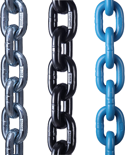
Chain Lashing Assemblies
A marine chain lashing assembly normally includes a chain, tensioning device, hooks or connecting fittings, and identification showing its applicable capacity.
Chain lashings are frequently used for heavy machinery, rolltrailers, steel structures, transformers, and other dense cargo because they provide high capacity in a compact assembly and tolerate demanding industrial environments.
The chain should be connected as a direct lashing between a verified cargo or rolltrailer point and a rated anchor. A direct lashing develops restraint through its longitudinal, transverse, and vertical force components.
Describing every chain lashing as simply “pulling the cargo down” is technically incomplete. A lashing running mainly across the unit can provide strong transverse restraint. A lashing running diagonally can contribute to both transverse and longitudinal restraint. A steep lashing may provide substantial downward force but less horizontal resistance.
Under the current Annex 13 method, a chain without a separately approved marked working value is assigned an MSL equal to 50% of its breaking strength.
For example:
Documented chain assembly breaking strength 200 kN
MSL derived at 50% 100 kN
This result only applies when the complete assembly, including hooks, tensioner, connectors, rolltrailer point, and deck eye, can carry at least 100 kN.
If a 100 kN chain is connected through an 80 kN rolltrailer point, the effective MSL of that complete load path is 80 kN.
Chains must not be twisted, knotted, heated, field-welded, shortened with bolts, or passed over an edge that causes link bending. Excess chain should be secured so it cannot contact tyres, moving parts, walkways, or adjacent cargo.
Lever and Ratchet Tensioners
The tensioning device removes slack and establishes the required lashing condition.
Lever tensioners operate through an over-centre mechanism. They can be applied quickly but contain stored energy during installation and release. The operator must remain outside the handle’s possible release path.
Ratchet tensioners provide progressive adjustment through a threaded mechanism. They allow controlled tightening and can be easier to adjust when the chain settles.
The tensioner must be compatible with the chain size, chain grade, end fittings, and required MSL. A 100 kN chain connected to a 60 kN tensioner becomes a 60 kN assembly.
The tensioner should be positioned so that it remains accessible for inspection without creating a projection or trip hazard. Its mechanism must be protected against unintended release.
A binder must not be tightened until its threads are nearly disengaged. Sufficient thread engagement must remain in both end fittings.
Extension Handles
A longer handle can increase the torque applied to a lever or ratchet tensioner. It can also overload the chain, tensioner, hook, deck eye, rolltrailer point, or cargo attachment without giving the operator a reliable indication of the resulting force.
Only a dedicated extension handle specifically approved for the tensioning device should be used. The manufacturer must define the permitted handle length and operating procedure.
Pipes, scaffold tubes, loose steel bars, or other improvised handle extensions must not be used.
An approved extension handle helps the operator apply the intended force. It does not increase the MSL of the chain lashing assembly.
Mechanized or Powered Chain Tensioning
A powered tensioning tool can accelerate the installation of large numbers of heavy lashings. Such equipment is particularly useful where manual operation would be slow or physically demanding.
The powered tool must be designed for the exact tensioning system. Its torque, hydraulic pressure, pneumatic pressure, or programmed setting must correspond to the required operating condition.
An ordinary impact wrench must not be applied to a standard load binder unless the binder manufacturer expressly permits it. Impact loading can damage threads, ratchet teeth, pins, or internal components and can generate uncontrolled tension.
Powered systems require calibration, functional checks, compatible sockets or interfaces, and a defined stop condition. Operators must be trained to recognize incomplete engagement, cross-threading, excessive tension, and damaged components.
Mechanized tightening improves installation efficiency but does not replace inspection or engineering calculation.
Heavy Web Lashings
Heavy web lashings may be used for project cargo or rolltrailer securing when their MSL, elongation, end fittings, tensioning system, environmental limits, and vessel approval match the application.
A heavy web lashing must not be described as having the same strength as a chain lashing without comparing their documented ratings. A 50 kN web lashing is not equivalent to a 100 kN chain simply because both are marketed as heavy-duty products.
Under the Annex 13 default relationship, a web lashing is assigned an MSL equal to 50% of its documented breaking strength unless an approved permissible working value is marked.
For example:
Documented web-lashing breaking strength 200 kN
MSL derived at 50% 100 kN
Web lashings are lighter than comparable chain assemblies and can be easier to handle. Their broad contact surface may also reduce marking of painted cargo.
However, synthetic webbing is more vulnerable to cutting, abrasion, heat, welding spatter, sharp steel edges, chemical contamination, and damage caused by rough deck surfaces.
Web lashings normally have different elongation characteristics from chain. When chain and web lashings are installed in parallel in the same direction, the less elastic component may accept load before the more elastic component begins to contribute.
Current Annex 13 guidance states that where securing devices with different elastic behaviour are used in the same direction, a more flexible device should be excluded from the calculation if it will not contribute to preventing initial movement.
Chain and web lashings must therefore not be assumed to share the force equally.
Steel Wire-Rope Lashings
Steel wire-rope lashings may be used for specific long, irregular, or fabricated cargo configurations when the complete assembly has an established MSL.
The rope construction, diameter, core, termination, thimble, ferrule, socket, tensioning device, and connection fittings all affect the assembly capacity.
Under Annex 13 default relationships:
Single-use wire-rope lashing MSL 80% of breaking strength
Reusable wire-rope lashing MSL 30% of breaking strength
The difference reflects the need to account for service condition and repeated use. The actual approved or marked MSL should be used where it is available.
Wire rope must be protected against sharp bending, crushing, kinking, abrasion, and damage at terminations. A lifting wire-rope sling is not automatically a maritime cargo-securing lashing.
Jacks and Support Stands
Jacks may be positioned beneath a rolltrailer to reduce movement, control deflection, and stabilize the platform during sea transport.
The jack must have adequate compression capacity, operating range, base area, head geometry, and mechanical locking. Its upper and lower contact points must be structurally capable of accepting the reaction.
A jack placed against an unreinforced section of the rolltrailer can deform the trailer rather than stabilize it. A small jack foot can also apply an unacceptable concentrated load to the vessel deck.
Jacks provide vertical support and can reduce movement in the rolltrailer structure. They do not replace the lashings required to resist longitudinal and transverse forces.
Jacks must be installed in the designated locations and adjusted without lifting the cargo unit into an unintended load distribution.
Where a vehicle suspension system is involved, the approved Cargo Securing Manual and vehicle instructions determine whether the suspension must be compressed, depressurized, or mechanically supported.
Rubber Friction Mats
Rubber mats can increase friction between machinery and a rolltrailer or between a suitable rolltrailer support and the vessel deck.
The current Annex 13 calculation method provides the following default friction coefficients:
Timber against timber, wet or dry μ = 0.4
Steel against timber μ = 0.3
Steel against rubber μ = 0.3
Dry steel against steel μ = 0.1
Wet steel against steel μ = 0.0
These values demonstrate why direct steel-to-steel contact is a weak basis for cargo security, particularly when the deck is wet.
For a 35-tonne machine, the simplified static friction term can be compared as follows:
Steel against rubber:
Friction contribution = 0.3 × 35 × 9.81
Friction contribution = approximately 103.0 kN
Dry steel against steel:
Friction contribution = 0.1 × 35 × 9.81
Friction contribution = approximately 34.3 kN
Wet steel against steel:
Friction contribution = 0.0 × 35 × 9.81
Friction contribution = 0 kN
This comparison does not constitute a complete securing calculation because vertical acceleration, tipping, lashing angles, wind, sea forces, and support conditions remain to be checked.
A higher friction value may only be used when supported by conservative certification and when the mat can withstand the local pressure and repeated shear loading.
Thin rubber sheet, conveyor-belt offcuts, damaged matting, or unidentified material should not be assigned a certified friction coefficient.
Oil, grease, water, paint dust, frost, rust scale, and welding debris can reduce performance. Mats should be clean, correctly positioned, and large enough to maintain contact beneath the intended support area.
Corner and Edge Protection
Corner protection prevents chain, wire rope, or webbing from damaging the cargo and prevents the cargo from cutting or crushing the lashing.
Web lashings require particular protection at sharp steel edges. The protector must be strong enough to resist the contact pressure and remain in position during vibration.
A thin plastic corner protector intended for packaging may not be suitable for a high-capacity marine lashing. Heavy-duty polymer profiles, reinforced rubber protectors, timber softeners, steel radius sections, or purpose-made protective saddles may be required.
Chain lashings may also require protection where direct contact could damage paint, insulation, composite materials, machined surfaces, or pressure-vessel coatings.
Corner protection does not increase lashing MSL. It preserves the condition and intended geometry of the system.
Cargo Nets and Secondary Restraint
Cargo nets can secure hoses, covers, tools, small components, packaged accessories, and irregular groups of lighter items carried on the rolltrailer.
A net should have documented capacity for its webbing or rope, junctions, border, end fittings, and attachment points.
Cargo nets must not be used as the primary restraint for a heavy transformer, machine, boat, or structural module unless the complete net system has been specifically engineered and rated for that cargo.
Secondary items should be secured independently so that failure of a toolbox, cover, hose bundle, or loose component cannot damage the principal lashings.
Shackles, D-Rings and Deck Eyes
Shackles, rings, deck eyes, turnbuckles, hooks, and connectors are load-bearing parts of the securing system.
Under Annex 13, mild-steel shackles, rings, deck eyes, and turnbuckles are assigned an MSL equal to 50% of breaking strength unless an approved value is marked.
When several components are connected in series, the lowest MSL controls the complete lashing.
For example:
Chain MSL 100 kN
Tensioner MSL 100 kN
Hook MSL 100 kN
Shackle MSL 80 kN
Rolltrailer securing point MSL 120 kN
Deck eye MSL 100 kN
The effective MSL of the complete system is 80 kN because the shackle is the weakest component.
Hooks must be designed so that they cannot disengage if the lashing temporarily becomes slack. Side loading, tip loading, and incorrect seating must be avoided.
Temporary welded fittings require an engineered design, established welding procedure, qualified welder, appropriate material, suitable inspection, and positioning that minimizes bending.
Core Maritime Securing Data
Current RoRo Vehicle Guidance
The 2020 revised international guidelines for road vehicles on RoRo ships establish the following reference values within their defined scope:
Road-vehicle mass range 3.5 to 40 tonnes
Articulated road-train maximum mass 45 tonnes
General longitudinal spacing of deck securing points not more than 2.5 m
Athwartship spacing of deck securing points 2.8 to 3.0 m
Minimum MSL of an individual deck securing point 100 kN
General minimum lashing MSL 100 kN
Vehicle securing points on each side not fewer than two and not more than six
These figures apply to the road vehicles covered by the guidelines. A rolltrailer carrying unusually large or heavy project cargo may fall outside those standard vehicle parameters and requires special consideration under the vessel’s Cargo Securing Manual and the Annex 13 calculation method.
The 100 kN figure must not be used automatically as the required capacity of every project-cargo lashing. The number and capacity must still be checked against the combined mass, centre of gravity, stowage location, vessel characteristics, expected conditions, and attachment geometry.
MSL, Breaking Strength and Calculated Strength
Maximum Securing Load, or MSL, defines the allowable load capacity of equipment used to secure cargo to a ship.
Minimum Breaking Load or nominal breaking strength represents the documented failure-related strength under specified test conditions. It is not the allowable securing load.
For the standard Annex 13 balance calculation:
Calculated Strength = MSL ÷ 1.5
A lashing with an MSL of 100 kN therefore contributes a calculated strength before directional factors of:
100 ÷ 1.5 = 66.7 kN
The calculation must then apply the relevant vertical and horizontal lashing-angle factors. It is incorrect to add the full 100 kN MSL of every diagonal lashing in every direction.
Lashing Angle
Current RoRo guidance describes lashings angled between approximately 30° and 60° to the deck as generally effective for securing road vehicles.
Annex 13 states that a transverse lashing angle to the deck greater than 60° should not be counted in its rule-of-thumb method. A steep lashing may still help resist tipping, but it becomes less effective against sliding.
Under the standard transverse balance method, a horizontal deviation greater than 30° from the transverse direction may require the lashing to be excluded from the transverse sliding balance.
Lashing geometry should therefore be shown on a drawing rather than described only as “chains on both sides.”
Rule-of-Thumb Method
Annex 13 provides a rule-of-thumb method under which the total MSL of the securing devices on each side of a cargo item, port and starboard, should equal the weight of the item in kilonewtons.
This method assumes transverse acceleration of 1g. It does not credit friction and does not compensate for poor angles or unequal force distribution.
The method requires suitable friction material, and the transverse lashing angle to the deck should not exceed 60°.
Worked Break Bulk Securing Example
The following example explains the calculation logic. It is not presented as a completed customer project and must not replace a vessel-specific calculation.
Assumed Cargo Data
Industrial machine mass 35 tonnes
Rolltrailer tare mass 10 tonnes
Combined sea-transport mass 45 tonnes
Candidate lashing MSL 100 kN
Candidate arrangement symmetrical port and starboard
Calculation method Annex 13 rule-of-thumb preliminary check
The machinery-to-rolltrailer system must first be calculated using the 35-tonne cargo mass.
The rolltrailer-to-deck system uses the combined 45-tonne mass.
Converting Mass to Weight
Weight = 45 × 9.81
Weight = 441.45 kN
Under the rule-of-thumb method, the total MSL on the port side should be at least 441.45 kN.
The total MSL on the starboard side should also be at least 441.45 kN.
Preliminary Lashing Quantity
When every complete lashing load path has an effective MSL of 100 kN:
Required quantity per side = 441.45 ÷ 100
Required quantity per side = 4.414
The preliminary result must be rounded up:
Port side 5 lashings
Starboard side 5 lashings
Total 10 lashings
The resulting nominal total MSL on each side is 500 kN.
This preliminary arrangement remains valid only if every chain, tensioner, hook, shackle, rolltrailer point, and deck point has an MSL of at least 100 kN.
Effect of a Lower-Rated Rolltrailer Point
If the rolltrailer securing points have an MSL of only 80 kN, every connected 100 kN chain becomes an 80 kN load path.
Required quantity per side = 441.45 ÷ 80
Required quantity per side = 5.518
The preliminary quantity becomes:
Port side 6 lashings
Starboard side 6 lashings
Total 12 lashings
Installing a stronger chain does not correct the lower rolltrailer-point capacity.
Limitations of the Example
The result does not prove compliance for a real shipment. The final plan must still verify:
Actual centre of gravity
Transverse tipping
Longitudinal sliding
Vertical acceleration
Lashing angles
Unequal load distribution
Cargo-to-rolltrailer restraint
Cargo and rolltrailer attachment strength
Rolltrailer concentrated loading
Vessel length and speed
B/GM relationship
Stowage height and position
Expected weather and sea conditions&l