High-density cargo concentrates substantial mass within a relatively small footprint. Cylindrical cargo introduces the additional possibility of rolling, rotating, tipping or gradually “walking” across the vehicle deck during transportation.
Steel coils, aluminium coils, wire rod, mill rolls, cable reels, paper rolls, pipes, pressure vessels, drums and other cylindrical industrial products therefore require more than a conventional tie-down arrangement. Their securing systems must control sliding, rolling, tipping, vertical movement, local deck pressure and the possibility of individual components separating from a bundle.
Typical applications include:
Steel and aluminium coil transportation
Wire rod and strip coil securing
Steel, concrete and plastic pipe transport
Cable reel and industrial drum shipment
Paper and tissue roll logistics
Mill roll and rotating equipment transportation
Pressure vessel and cylindrical module securing
High-density casting, die and counterweight transport
Road transportation exposes these products to emergency braking, cornering, vibration, road camber, potholes and repeated changes in trailer attitude. A cylindrical object that appears immovable while the vehicle is stationary can develop sufficient momentum to climb over an undersized chock, crush its supporting timber or break through an inadequately rated trailer structure.
A complete solution must therefore combine a suitable vehicle, verified axle-load distribution, purpose-designed bunks or cradles, retained chocks, controlled friction, correctly arranged chains or web lashings, rated anchor points and a safe loading and unloading procedure.
Why High-Density and Cylindrical Cargo Requires Special Control
High Mass Does Not Guarantee Stability
The belief that a heavy object will remain stationary because it cannot be moved by hand is unsafe.
The friction force available between cargo and the trailer is proportional to the normal load, but the inertial force created during braking and cornering is also proportional to cargo mass. Increasing mass increases both forces. A heavy load is therefore not self-securing.
A compact steel coil can also apply extremely high pressure to a small area of the trailer deck. The trailer may remain within its overall payload rating while a local deck plate, cross-member or timber support is overloaded.
The following data must be verified before selecting the restraint system:
Individual cargo mass
Total shipment mass
Outside diameter and width
Internal eye or bore diameter
Centre-of-gravity position
Cargo material and surface condition
Transport orientation
Approved contact and support areas
Allowable local bearing pressure
Packaging and banding condition
Trailer deck and axle capacities
Anchor-point locations and ratings
For coils and reels, the bore diameter is important because it determines whether a chain, wire-rope lashing or protective sleeve can pass through the eye without contacting a sharp edge or damaging the product.
Sliding, Rolling and Tipping Are Different Failure Modes
Sliding occurs when the horizontal transportation force exceeds the resistance provided by friction, blocking and lashings.
Rolling occurs when a cylindrical load rotates around its contact point or climbs over a chock, bunk or cradle edge.
Tipping occurs when the overturning moment produced by horizontal force exceeds the restoring moment created by cargo weight and support width.
These failure modes must be checked independently. A system that stops sliding may not stop rolling. A system that prevents rolling may still allow a narrow coil to tip sideways. A high-friction mat does not replace a cradle, and a cradle does not automatically provide forward restraint.
Packaging Bands Are Not Vehicle Restraints
Bands around a steel coil, pipe bundle or wire rod coil normally maintain the product’s packaged form. They do not secure the cargo to the vehicle unless they have been specifically engineered, rated and incorporated into the transport restraint system.
Damaged or insufficient coil bands can allow telescoping, spreading or separation even when the complete coil remains chained to the trailer. Product integrity and vehicle restraint must therefore be assessed separately.
Tarpaulins and weather covers perform the same limited function. They protect or contain the cargo but cannot be credited as structural restraint.
Cargo Orientation and Its Effect on the Securing Method
The orientation of a coil or roll is normally described by the direction of its central eye or axis.
Eye Vertical
An eye-vertical coil stands on one circular face with its axis vertical.
This orientation eliminates conventional fore-and-aft rolling, but the coil can slide or tip in any horizontal direction. A narrow coil with a large diameter has a smaller supporting footprint relative to its centre-of-gravity height and may be particularly sensitive to tipping.
The securing system must control forward, rearward and lateral movement. Diagonal lashings, transverse restraint, friction material and positive forward blocking may be required.
The load should not be placed directly over weak decking or unsupported areas. A load-spreading platform may be necessary because the entire mass is transmitted through the bottom coil face or supporting pallet.
Eye Crosswise
An eye-crosswise coil has its axis running across the width of the vehicle. The coil can therefore roll toward the front or rear of the trailer.
This orientation requires a coil bunk, cradle, retained wedges or another positive anti-roll system. For large metal coils governed by United States federal rules, the anti-roll device must support the coil off the deck and must not be capable of becoming loose in transit.
At least one through-eye tiedown is required to restrain forward movement and at least one through-eye tiedown is required to restrain rearward movement under the applicable United States metal-coil rule. Forming an X-pattern through the eye when viewed from above is specifically prohibited for coils transported eye crosswise.
The through-eye arrangement must not damage the inner coil edge. Protective sleeves, shaped edge protectors or other engineered interfaces may be needed.
Eye Lengthwise
An eye-lengthwise coil has its axis parallel to the direction of travel. Its natural rolling direction is therefore lateral.
This orientation requires substantial lateral anti-roll support. The bunk or cradle must be structurally connected to the trailer and capable of transmitting the load into suitable cross-members or main beams.
United States federal rules provide several permitted arrangements for individual metal coils transported eye lengthwise. Depending on the selected option, these can include retained anti-roll support, diagonal or straight through-eye tiedowns, transverse top-over tiedowns and blocking or friction material for longitudinal control.
The selected option must be followed as a complete configuration. Components from different regulatory options should not be combined casually without confirming that the resulting system satisfies every applicable requirement.
Cylindrical Cargo Without an Eye
Pressure vessels, mill rolls, solid shafts and some drums do not have a bore through which a lashing can pass.
These products normally require shaped saddles, end stops, chocks and direct lashings connected to approved transport lugs or structural support frames. Chains must not be wrapped around polished journals, machined sealing surfaces, pipe nozzles or thin vessel shells.
Where no suitable transport points exist, an engineered transport frame may be required before the cargo can be safely accepted.
Application-Specific Securing Solutions
Steel and Aluminium Coils
Steel coils combine high density, low metal-to-metal friction and exposed edges that can damage synthetic lashings. Marked transport chains are therefore commonly preferred.
A typical system can include a structural coil bunk, retained hardwood or steel chocks, anti-slip material, through-eye chains, transverse chains, compatible load binders and verified trailer anchor points.
The bunk must be sized for the coil diameter and mass. A coil should sit symmetrically without bottoming out against an unintended deck surface. Contact areas must distribute pressure without crushing the product edge.
Chocks must not rely on friction alone to remain in position. They should be retained by a coil rack, pocket, pin, structural channel or another positive arrangement.
Chains passing through a coil eye should be protected from sharp internal edges. The protection must be capable of carrying the contact pressure without splitting, moving or creating an unacceptable reduction in lashing capacity.
Surface-finished, painted or aluminium coils may require wider protective interfaces. A heavy web lashing may be suitable when its capacity, edge protection and contact pressure have been verified, but an unprotected textile strap should not be placed against a sharp metal edge.
Wire Rod and Strip Coils
Wire rod coils can deform, spread or telescope because they are not always as geometrically rigid as sheet-metal coils. Packaging bands maintain the coil shape but should not be treated as trailer tiedowns.
The load should be supported in a bunk or stable rack that prevents individual coils from rolling and prevents adjacent coils from moving into each other. Side stanchions may provide additional containment when they are structurally rated for the expected load.
The restraint plan must consider whether the cargo will settle during the journey. As wire rod beds into dunnage and neighbouring coils, initially tensioned chains may lose tension. Early in-transit inspection is therefore particularly important.
Chains and hooks should not be allowed to become trapped between individual turns of wire. Local contact can damage the product, prevent correct tension distribution and create a cutting surface.
Steel, Concrete and Plastic Pipes
Pipes require control against rolling, longitudinal movement and lateral spreading.
Large individual pipes are normally placed in shaped cradles, on bunks with retained chocks or between rated stanchions. Longitudinal end stops may be necessary where braking forces cannot be carried by lashings alone.
Multiple layers require separators and stable nesting. The lowest layer must be positively contained because failure of one bottom pipe can destabilize the entire stack.
Bundle bands keep pipe groups together but do not replace vehicle restraint. The entire bundle must be secured to the trailer, and the design should consider what happens if one packaging band fails.
Thin-wall or coated pipes can be damaged by concentrated chain pressure. Web lashings with sleeves, wide corner protectors or purpose-built saddles may be more appropriate, provided the webbing is protected from pipe ends and other sharp surfaces.
Concrete pipes may be subject to commodity-specific transport regulations. Their high mass, brittle edges and concentrated support reactions require appropriately sized bunks, chocks and tiedowns. General steel-coil rules should not be assumed to cover concrete pipe.
Cable Reels, Drums and Spools
Cable reels are normally transported standing on their flanges with the reel axis horizontal, unless the manufacturer specifies another orientation.
Both flanges should be adequately supported. Chocks must restrain rolling in both directions and must be positively retained. Direct lashings should act through an approved central shaft, structural reel member or designated transport point.
Chains or straps should not bear directly on the wound cable, fibre-optic product or delicate flange edge. A lashing that compresses the cable can damage the product while still failing to restrain the structural reel.
Wooden reels require inspection for cracked flanges, loose fasteners, decay and damaged hubs. A lashing cannot compensate for a reel that is no longer structurally capable of carrying transportation forces.
Steel drums containing liquids can experience internal movement. Drums should be arranged in suitable racks, pallets or locators and secured against rolling, sliding and separation. Closures, filling caps and protective fittings must not be used as lashing points.
Hazardous contents introduce additional packaging, segregation, marking and dangerous-goods requirements that are separate from cargo restraint.
Paper and Tissue Rolls
Paper rolls are surface-sensitive and can be crushed or marked by chains. Heavy web lashings, broad corner protectors and high-friction material are usually more appropriate.
Paper rolls transported vertically can gradually walk across a low-friction deck under repeated vibration. Top-over lashings alone may therefore be insufficient. Positive fit, blocking, high-friction surfaces or a suitable transport frame may be required.
Moisture can change both the strength of paper packaging and the friction condition. Wet packaging must not be assigned the same assumed performance as clean, dry material without supporting data.
The strap location should distribute pressure without crushing the roll edge. A rigid pressure-spreading member may be needed where a narrow strap would deform the product.
Mill Rolls, Shafts and Rotating Equipment
Mill rolls and industrial shafts are extremely dense and may include precision-machined journals.
They should be carried in engineered saddles that contact approved barrel areas rather than finished journals. End stops and direct lashings should control longitudinal motion. Lateral chocks or a shaped cradle should control rolling.
Chains must not contact bearing surfaces. Soft packing alone is normally insufficient because it can compress, extrude or move under high line pressure. Shaped steel or timber supports with replaceable protective liners are more reliable.
High-Density Castings, Dies and Counterweights
Dies, castings, counterweights and forged components may not be cylindrical, but they produce similar concentrated-load problems.
Their compact shape can overload a trailer locally and make visual weight estimation unreliable. Load-spreading beams, direct chain lashings, positive blocking and verified axle calculations are commonly required.
Cast holes and openings must not be treated as lashing points unless their load capacity and direction have been approved. Rough casting edges can also cut webbing or create severe chain bending.
Building the Complete Restraint System
Coil Bunks, Cradles and Chocks
A coil bunk or cradle establishes stable cargo geometry and transfers rolling forces into the trailer.
Its design should consider the cargo diameter, mass, centre-of-gravity height, contact pressure, support spacing, chock angle, material strength, fastening method and trailer structure.
Timber used as support material must be structurally sound and free from splitting, decay and defects that compromise its load-bearing function. The selected dimensions must come from the load calculation rather than from general workshop availability.
Steel cradles require sufficient plate thickness, stiffening and connection capacity. Welds and retaining pins must carry the calculated forces into the structural trailer frame.
A chock is ineffective if the coil can crush it, push it along the deck or climb over it. A chock is also ineffective if its retaining pocket or fastener fails before the chock material reaches its own capacity.
Direct Lashings
Direct lashings resist cargo movement through the directional component of their tension.
For a lashing installed at an elevation angle (�lpha) above the deck and a plan-view angle (�eta) away from the required direction, an idealized component in that direction is:
[
F_{ ext{direction}}=Tcos�lphacos�eta
]
A high-capacity chain installed at an ineffective angle may contribute substantially less restraint in the required direction than expected.
The calculation must use the applicable standard’s method. The rated WLL or LC should not simply be inserted as lashing pretension. Pretension, allowable force and breaking strength describe different conditions.
Top-Over Lashings
Top-over lashings increase normal force and therefore increase friction. They can also provide vertical restraint and help prevent a roll from bouncing out of its cradle.
Their effectiveness depends on achievable pretension, lashing angle, edge friction and the condition of the cargo-to-deck interface.
For an extremely heavy steel coil, a top-over chain should normally be treated as one part of a combined system. It should not replace through-eye restraint and positive anti-roll support where these are required.
Friction Material
High-friction mats can reduce the force that must be resisted by lashings and blocking. Their performance depends on material, surface pressure, cleanliness, moisture, oil, temperature and the interacting surfaces.
The mat must not be crushed beyond its rated pressure by a high-density support point. Small mat pieces placed under narrow coil runners may experience much higher pressure than a large mat beneath a pallet.
Only a documented friction coefficient applicable to the actual materials and conditions should be used in an engineering calculation.
Anchor Points and Trailer Structure
The complete restraint path includes the cargo, cradle, lashing, tensioner, connector, trailer anchor, anchor weld and supporting trailer structure.
The assembly rating is limited by its weakest component.
A side rail or rope hook should not be used merely because a chain can be connected to it. It must have a verified capacity in the actual loading direction.
Coil trailers with purpose-designed wells, bunks and anchor points are generally preferable to standard flatbeds for repetitive heavy-coil transportation. The equipment should still be inspected for cracking, deformation, corrosion and loose retaining components.
Selecting Chains, Wire Ropes, Web Lashings and Accessories
Transport Chains
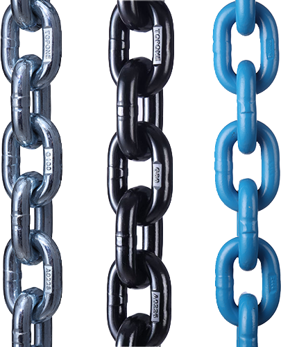
Chains are normally the preferred lashing product for steel coils, mill rolls, pipe bundles and other heavy metal cargo because they provide high capacity in a compact assembly and resist abrasion better than unprotected textile webbing.
The chain grade, diameter, WLL or LC, hook, shortening device and binder must form a compatible assembly. Capacity must be established from markings and manufacturer documentation rather than diameter alone.
Grade 70 is commonly identified as transport chain in North American applications. Grade 80 and Grade 100 alloy chains can offer higher strength, but their use must be supported by the applicable lashing rating and complete assembly documentation.
A lifting-chain certificate does not automatically establish road-lashing capacity. Cargo-control chains must not be used for lifting unless separately designed and certified for that purpose.
Load Binders
Ratchet binders allow progressive chain adjustment and are suitable where controlled tensioning is required.
Lever binders use an over-centre mechanism and can release stored energy suddenly. Operators must remain outside the potential handle path and follow the manufacturer’s operating instructions.
Binders should match the chain size and grade. Improvised handle extensions must not be used unless the product has been designed and approved for that operation.
After tensioning, handles, adjustment mechanisms and excess chain should be retained against vibration.
Steel Wire-Rope Lashings
Steel wire rope can be selected for long through-eye routes, large reels or irregular cylindrical cargo where chain routing is difficult.
Its capacity depends on the rope construction, wire grade, core, termination, bending radius and connection fittings. Sharp bending around a coil eye can reduce capacity and damage the rope.
Wire rope should be rejected for kinks, birdcaging, crushing, corrosion, broken wires or damaged terminations according to the applicable standard and manufacturer criteria.
Heavy Web Lashings
Heavy web lashings are suitable for paper rolls, coated pipes, finished aluminium products and other cargo requiring a broad, non-metallic contact surface.
The webbing, stitching, ratchet, hooks and label form one rated assembly. Colour is not a capacity rating.
Web lashings must be protected from sharp coil edges, pipe ends, welding spatter, hot surfaces and incompatible chemicals. The protective sleeve or corner protector must remain in position and withstand the actual contact pressure.
A heavy web-lashing system can only replace a chain when its documented capacity, geometry, environmental resistance and complete load path satisfy the calculation.
Compatible Supporting Products
Chains, wire ropes and web lashings can be combined with:
Structural coil bunks
Retained steel or hardwood chocks
Anti-slip mats
Rated D-rings and lashing eyes
Compatible hooks and shackles
Load binders and approved tensioners
Edge protectors and chain sleeves
Pipe stanchions and end stops
Load-spreading beams and deck plates
Reel shafts and transport frames
Every product must be matched to the same load case. A rated chain connected to an unverified chock or trailer side rail does not create a rated system.
Core Engineering Data and Transparent Calculation
United States Metal-Coil Requirements
49 CFR §393.120 applies to one or more metal coils that individually or collectively weigh at least 2,268 kg, or 5,000 lb.
For eye-crosswise coils transported on a flatbed, sided vehicle or intermodal container with anchor points, the rule requires an anti-roll arrangement that supports the coil off the deck and cannot become loose. At least one through-eye tiedown must restrain forward movement and at least one must restrain rearward movement.
Whenever practicable, the forward and rearward tiedowns should make an angle no greater than 45 degrees with the vehicle floor when viewed from the side.
An X-shaped tiedown arrangement through the eye of an eye-crosswise coil, when viewed from above, is prohibited.
These are United States requirements. Other jurisdictions use their own regulations and adopted standards.
General United States Performance Criteria
Under 49 CFR §393.102, tiedown assemblies must remain within their breaking-strength ratings under the following separately applied conditions:
0.8 g deceleration forward
0.5 g acceleration rearward
0.5 g acceleration laterally
For working load limit, the separately applied conditions are:
0.435 g deceleration forward
0.5 g acceleration rearward
0.25 g acceleration laterally
Cargo not fully contained within the vehicle structure must also receive downward force equivalent to at least 20 percent of its weight.
Current British Guidance
Current British government guidance states that a road cargo-securing system should withstand force equivalent to the entire cargo weight in the forward direction and half the cargo weight laterally and rearward.
This is different from the United States criteria. Values from different jurisdictions must not be mixed within one calculation.
Assumed Steel-Coil Calculation
The following is a transparent hypothetical example. It is not a customer case and is not a complete lashing design.
Assume an eye-crosswise steel coil has the following verified data:
Mass: 15,000 kg
Outside diameter: 1.80 m
Radius: 0.90 m
Width: 1.20 m
Candidate through-eye chains: two complete assemblies
Documented WLL per assembly: 10,000 lbf
Assumed certified friction coefficient for preliminary screening: 0.30
The cargo weight force is:
[
W=15{,}000 imes9.81=147.2 ext{ kN}
]
The 0.8 g forward load-level demand is:
[
F_{ ext{forward}}=147.2 imes0.8=117.7 ext{ kN}
]
The 0.5 g rearward or lateral demand is:
[
F_{ ext{rear/lateral}}=147.2 imes0.5=73.6 ext{ kN}
]
The 20 percent downward-force requirement is:
[
F_{ ext{downward}}=147.2 imes0.2=29.4 ext{ kN}
]
If a friction coefficient of 0.30 can legitimately be used, the simplified sliding resistance from cargo weight alone would be:
[
F_{ ext{friction}}=0.30 imes147.2=44.2 ext{ kN}
]
The preliminary forward-force difference would therefore be:
[
117.7-44.2=73.5 ext{ kN}
]
This result shows why the coil’s weight and friction cannot be treated as a complete restraint system. It does not prove that 73.5 kN is the final required chain or chock capacity. Rolling geometry, lashing direction, pretension, cradle reactions and the applicable calculation method must still be evaluated.
Aggregate WLL Check
The coil mass in pounds is approximately:
[
15{,}000 imes2.20462=33{,}069 ext{ lb}
]
The minimum aggregate tiedown WLL under the United States one-half-weight rule is:
[
33{,}069 imes0.5=16{,}535 ext{ lbf}
]
If both candidate through-eye tiedowns run from an anchor on one side of the vehicle, through the coil eye and to an anchor on the opposite side, each may be credited at its full WLL under the applicable aggregate-WLL counting rule.
The candidate aggregate WLL would be:
[
2 imes10{,}000=20{,}000 ext{ lbf}
]
This exceeds the 16,535 lbf aggregate minimum.
It does not automatically approve the arrangement. The system must still include the required forward and rearward geometry, a compliant anti-roll cradle, adequate downward control, verified anchors and satisfaction of the performance criteria.
If the same two tiedowns instead ran only from a vehicle anchor to a cargo anchor, only half of each WLL would be counted:
[
2 imes0.5 imes10{,}000=10{,}000 ext{ lbf}
]
That arrangement would fail the aggregate-WLL requirement.
Illustrative Chock-Height Screening
The following calculation only illustrates why arbitrary timber size is not an engineering basis. It does not replace a cradle calculation.
For an ideal rigid cylinder initially supported on a level surface, with a rigid chock of height (h), radius (R) and no friction, the approximate horizontal force required to begin rolling over the chock can be expressed as:
[
�rac{F}{W}=
�rac{sqrt{2Rh-h^2}}{R-h}
]
For an assumed horizontal force equal to (0.8W), the idealized minimum geometric ratio becomes:
[
�rac{h}{R}
1-�rac{1}{sqrt{1+0.8^2}}
0.219
]
For the assumed 0.90 m coil radius:
[
h=0.219 imes0.90=0.197 ext{ m}
]
The idealized result is approximately 197 mm.
This does not mean that a 197 mm timber is automatically acceptable. The simplified model ignores friction, dual-cradle contact, chain forces, timber crushing, fastener capacity, dynamic impact, coil-edge strength, deck deformation and the requirement for some coil arrangements to remain supported off the deck. It demonstrates that a shallow loose timber strip cannot be selected solely by visual judgment.
Published Accident Case
On 18 June 1998, a passenger train struck the second flatbed semitrailer of a long combination vehicle at a highway-rail crossing near Portage, Indiana.
The trailer carried a steel coil weighing 38,030 lb, approximately 17.25 tonnes. The coil was 72 in in outside diameter and 41 in wide. According to the investigation, the rear coil was secured by a single chain.
When the train struck the trailer, the chain broke. The coil entered the front of the passenger railcar and travelled approximately 34 ft into the passenger compartment. Three people were killed and five sustained minor injuries.
The investigation stated that, under the regulations discussed in the report, three 3/8 in Grade 7 chains with a combined WLL of 19,800 lb would have been required for the 38,030 lb coil. Investigators calculated that even this three-chain regulatory arrangement would probably have failed by a factor of approximately eight under the exceptional train-impact forces.
The probable cause of the overall accident concerned unresolved hazards at the railway crossing, not normal road braking or cornering.
The case establishes two important boundaries.
<span s