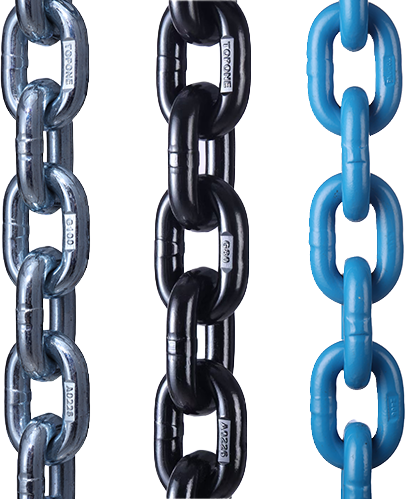
Heavy haulage and out-of-gauge transportation projects regularly move transformers, refinery modules, mining equipment, crawler cranes, pressure vessels, steel structures and complete industrial assemblies between factories, construction sites, ports and processing facilities.
Typical applications include:
Heavy haulage transport
Modular cargo shipment
Flatbed and low-bed trailer securing
Industrial project logistics
Oversized equipment movement
Transformer and power equipment transportation
Mining and construction machinery relocation
Long-distance road transportation exposes cargo to emergency braking, acceleration, cornering, road camber, vibration, potholes, uneven ground and repeated changes in trailer attitude. These forces can cause a load to slide, roll, tip, settle into its supporting material or loosen an initially tensioned lashing system.
A reliable heavy haulage solution therefore cannot be created simply by placing several chains around the cargo. It must integrate verified cargo data, trailer selection, axle-load distribution, structural support, route engineering, positive blocking, friction management, rated lashing equipment, inspection procedures and a controlled unloading plan.

What Makes Heavy Haulage and OOG Transport Different?
Heavy haulage and OOG transport are related, but they are not identical.
A heavy-haul movement is primarily controlled by mass, concentrated bearing loads, axle-group capacities, bridge limits and vehicle stability. An OOG movement is primarily controlled by the combined height, width, length or overhang of the cargo and transport vehicle. One consignment may be extremely heavy while remaining within the normal road envelope. Another may be relatively light but too long or too wide for standard transport.
Both conditions may exist in the same project.
The Transport Envelope Must Be Verified
The relevant transport envelope is not the dimension of the cargo alone. It is the complete loaded combination, including the cargo, support stools, transport frame, dunnage, low-bed or flatbed trailer, suspension position, wheels, gooseneck and any projecting restraint equipment.
Before equipment selection, the transport engineer normally requires the cargo’s verified mass, centre-of-gravity position in three axes, overall dimensions, approved support points, allowable bearing loads, transport orientation, structural lashing points and any prohibited contact areas.
The centre-of-gravity height is especially important. Two loads of equal mass may require completely different restraint systems if one has a low, wide support base and the other has a narrow footprint with a high centre of gravity.
Drawings should also identify removable parts, projecting nozzles, control cabinets, hydraulic cylinders, cooling equipment, lifting lugs, transport lugs and surfaces that cannot accept chain or webbing contact. A lifting lug designed for a predominantly vertical crane load must not automatically be treated as a road-transport lashing point. Its allowable load direction and capacity must be confirmed by the cargo manufacturer or responsible engineer.
Route Engineering Is Part of Cargo Control
A sufficiently strong lashing system cannot compensate for an unsuitable route.
The route survey should consider bridge capacity, lane-specific overhead clearance, tunnels, gantries, utility cables, railway crossings, road gradients, side slopes, tight intersections, roundabouts, swept paths, culverts, temporary roadworks, street furniture and available stopping locations.
Clearance must be checked against the actual loaded height and width, not a preliminary cargo drawing. Where a bridge or tunnel has a curved or inclined profile, clearance can vary between lanes and across the width of the same lane.
Permits, police or escort requirements, approved travel windows, adverse-weather restrictions and utility-company coordination depend on the countries and local authorities involved. Road conditions can also change after a survey, so critical clearances and restrictions should be reconfirmed before the movement begins.
Trailer Selection Must Follow the Load Data
Low-bed trailers reduce loaded height and normally help lower the combined centre of gravity. However, they still require confirmation of deck capacity, concentrated bearing loads, ramp clearance and axle distribution.
Flatbed trailers provide convenient side access for loading and lashing but create a higher transport envelope. Step-deck and extendable trailers may be more suitable for tall or long cargo, although extension changes trailer stiffness, support locations and turning geometry.
Multi-axle hydraulic modular trailers can distribute very high loads over numerous axle lines and can control platform level during slow project movements. Their suspension travel and steering geometry must still be included in the clearance and stability assessment.
The trailer’s total payload rating is not sufficient by itself. The engineer must also confirm local deck strength, main-beam loading, gooseneck or kingpin load, individual axle-group load and the capacity and direction of every lashing point intended for use.

Cargo and Trailer Selection by Application
Transformer Transportation
Power transformers combine very high mass with sensitive internal and external components. The main tank should be supported at transport points approved by the transformer designer, normally through an engineered base, skid or load-spreading arrangement.
Chains must not be passed over bushings, radiators, cooling pipes, conservators, control cabinets or sheet-metal tank surfaces. These components are not structural lashing points and may be damaged long before the chain reaches its rated capacity.
Direct lashings should connect approved transformer transport points to verified trailer anchors. The load path should transfer forces into the transformer base and the trailer’s structural members without distorting the tank.
Bushings, radiators and other projecting components may be removed and packed separately when required by the transformer manufacturer. This is an equipment-specific decision and must not be assumed by the carrier.
Shock or tilt recorders can be used when required by the purchase specification, insurer or transformer manufacturer. Their alarm thresholds must come from the equipment designer. A generic acceleration limit should not be invented for all transformers.
Refinery Modules and Process Equipment
Refinery modules, pipe racks, pressure vessels and process skids often have large dimensions but relatively flexible supporting structures. Nozzles, flanges, piping, handrails, cable trays and access platforms must not be used as restraint points.
The preferred approach is to transfer road forces through a temporary transport frame, main skid beams or structural nodes approved by the module engineer. Where a long module can deflect, the support arrangement must consider trailer bending, road camber and differential axle movement.
Pressure vessels and cylindrical process equipment require engineered saddles, chocks or cradles to prevent rolling. The cradle must be restrained against movement and must distribute the concentrated load into suitable trailer structure. Lashing chains supplement the cradle; they should not be expected to replace positive anti-roll support.
Mining and Construction Equipment
Excavators, drilling machines, loaders, dozers and mining vehicles are commonly secured with direct chain lashings attached to manufacturer-approved tiedown points.
Buckets, booms, blades, hydraulic shovels and similar attachments should be completely lowered where practicable and separately restrained when their own movement could create a hazard. Articulated machines need a mechanical articulation lock or another approved method to prevent movement at the joint.
Parking brakes, transmission engagement and hydraulic pressure are not substitutes for cargo restraint. Hydraulic systems can leak down, tyres can deflect and tracked equipment can settle into dunnage during transportation.
Mud, oil, ice and loose material on tracks, tyres or the trailer deck make friction unreliable. Contact areas should therefore be cleaned before the securing calculation relies on friction. Chocks, blocking or track stops should be used where the transport design requires positive resistance.
Under United States federal rules, a wheeled or tracked heavy vehicle individually weighing at least 4,536 kg, or 10,000 lb, requires a minimum of four tiedowns. This is only a minimum quantity requirement. The working load limit, attachment-point capacity, lashing geometry and directional performance criteria must still be satisfied.
Crawler Crane and Crane Component Transportation
Crawler cranes are normally dismantled into transportable sections such as crawler frames, counterweights, boom sections, hook blocks and the machinery deck. Each section presents a different restraint problem.
Counterweights are dense and create high concentrated loads. They should be supported and blocked so they cannot slide or overturn. Boom sections are comparatively light but long and susceptible to local damage; they normally require shaped saddles, distributed support and web lashings or protected chains positioned at structural nodes.
Hook blocks, sheaves and loose reeving components must be prevented from swinging or rotating. A retaining arrangement is required even when the main component appears stable on its support frame.
Industrial Machinery and Fabricated Assemblies
Machinery with a rigid base can often be secured through transport holes or dedicated lashing brackets. Machinery with sheet-metal enclosures, precision guideways, exposed shafts or painted finishes requires protected contact areas and carefully controlled lashing geometry.
If an assembly has a narrow base or elevated centre of gravity, overturning may govern the design before sliding. Wider support beams, temporary transport frames or lateral bracing may be required. Adding stronger chains alone does not correct an unstable support geometry.
Building a Complete Cargo Restraint System
A dependable system normally combines positive support, direct restraint and controlled friction. Each element performs a different function.
Blocking, Chocks and Cradles
Blocking transfers longitudinal or lateral force directly from the cargo into the trailer structure. Chocks and cradles prevent wheels, cylinders and rounded components from rolling.
Blocking is only effective when both the block and its attachment to the trailer can transmit the design force. Timber placed against cargo but not adequately retained may move with the load. A block fixed only to a thin deck plate cannot be credited with the capacity of the trailer’s main frame.
Support beams and dunnage must also withstand bearing pressure without crushing. Small-footprint cargo can exceed the local deck capacity even when its total mass is below the trailer payload rating. Load-spreading plates or engineered beams may therefore be required.
Friction and Anti-Slip Material
Friction can reduce the restraint force that must be supplied by blocking and lashings, but it should only be credited when the calculation method permits it and the contact conditions are controlled.
Anti-slip mats are commonly used between cargo supports and the trailer deck. Their declared coefficient of friction, allowable surface pressure, temperature range and compatibility with oil or water should be verified from product documentation.
A published friction value for clean, dry material should not be used after the interface becomes wet, oily, muddy, icy or contaminated with loose scale. If the interface cannot be controlled, the restraint plan should use a conservative value or avoid depending on friction.
Direct Lashing and Top-Over Lashing
Direct lashings connect a cargo point to a trailer anchor and resist movement through the directional component of the lashing force. They are normally preferred for heavy machinery, transformers and industrial modules with approved lashing points.
Top-over lashings mainly increase downward force and therefore increase friction. They can be useful for stable cargo with broad contact surfaces but are less suitable as the only restraint for an extremely heavy, high-centre-of-gravity or low-friction load.
Lashing angle is fundamental. In a simplified direct-lashing model, if (T) is the lashing force, (�lpha) is the angle above the deck and (�eta) is the plan-view deviation from the required restraint direction, the useful component in that direction is:
[F_{ ext{direction}} = T imes cos�lpha imes cos�eta]
A chain may therefore have a high rated capacity but deliver a relatively small longitudinal component when installed at an ineffective angle. This equation only illustrates the geometric relationship. A complete calculation must also address friction, elasticity, cargo movement, blocking, pretension and the applicable regulatory method.
The Complete Load Path and the Weakest Component
The restraint path normally consists of:
Cargo transport point
Shackle, hook or connector
Chain, wire rope or web lashing
Load binder or tensioning device
Trailer D-ring or lashing point
Welded support and trailer structure
The rating of the complete path cannot exceed its weakest component. A high-strength chain does not increase the capacity of an undersized hook, damaged binder, unverified cargo lug or weak trailer D-ring.
Side loading is also important. A hook or shackle rated for straight loading may have a lower allowable capacity, or no approved capacity, when loaded across its body. The actual connection direction must agree with the manufacturer’s instructions.
Selecting Chains, Wire Ropes, Web Lashings and Accessories
Transport Chains
Chain lashings are normally the first choice for tracked equipment, steel structures, transformer bases and other heavy cargo with approved structural attachment points.
Chain performs well in dirty and abrasive environments and can provide high capacity in a compact assembly. It is less vulnerable to edge cutting than synthetic webbing, although chains and hooks can still be damaged by severe bending, twisting or impact.
Grade 70 is widely identified as transport chain in the North American market. Higher-strength Grade 80 or Grade 100 alloy chains are also available, but a grade number or chain diameter alone does not establish the capacity of a complete lashing assembly. The chain, shortening device, hook, binder and end fittings must be marked, compatible and rated for the intended cargo-control application.
European lashing products may be marked with lashing capacity, commonly shown as LC, while North American products commonly use working load limit, or WLL. LC, WLL, minimum breaking force and proof-test force are different terms and should not be treated as interchangeable without the applicable standard and manufacturer’s documentation.
A lifting-chain rating must not automatically be used as a road-lashing rating. Likewise, cargo-control chains and binders must never be used for lifting unless the entire assembly is separately designed, certified and marked for lifting service.
Ratchet and Lever Load Binders
A binder tensions the chain and removes slack from the system.
Ratchet binders provide gradual adjustment through a threaded mechanism. Lever binders use an over-centre action and can contain significant stored energy during opening and closing. Both types must be operated from a stable position and within the manufacturer’s instructions.
The binder must match the chain size and grade. Handle extensions, impact tools or improvised pipes must not be used unless the tensioning system has been specifically designed and approved for that method. Excessive handle force can overload the binder, chain, cargo point or trailer anchor before the operator sees visible damage.
Binder handles and loose chain ends should be retained so that vibration cannot allow them to open, unwind or strike adjacent equipment.
Steel Wire-Rope Lashings
Steel wire-rope lashings can be appropriate for long restraint paths, irregular cargo geometry and applications where greater flexibility than chain is required. They are used with rated end terminations, thimbles, tensioners and connection fittings.
Wire rope should not be knotted or sharply bent around small edges. Bend radius, rope construction, core type and end termination influence its available capacity. Kinks, crushing, birdcaging, broken wires, corrosion and damaged ferrules or sockets require assessment under the applicable discard criteria.
Wire rope is not automatically better than chain for heavy cargo. It becomes the appropriate choice when its flexibility, routing and documented assembly rating solve a defined engineering problem.
Heavy Web Lashings
Heavy-duty web lashings are useful where the cargo has finished, coated or easily damaged surfaces. Their wide contact area and low weight make them easier to position around large machinery and fabricated components.
A properly rated heavy web-lashing assembly can provide substantial restraint, but ordinary commercial straps must not be assumed to have chain-equivalent capacity. The webbing, stitching, ratchet, hooks, label and protective accessories form one rated system.
Webbing is vulnerable to sharp edges, abrasion, hot surfaces, welding spatter and some chemicals. Corner protectors and sleeves should be used to prevent cutting and to distribute pressure. Edge protection must remain in position throughout the journey and must not introduce a new low-friction sliding surface unless this has been considered in the calculation.
Polyester is common in road lashing systems, while other synthetic materials may also be used. Their behaviour in acids, alkalis, solvents and elevated temperatures differs. Material compatibility must be checked against the actual exposure rather than inferred from strap colour.
Supporting Products
Direct lashings can be combined with rated D-rings, lashing eyes, clevis hooks, grab hooks, shackles, chain-shortening devices and transport brackets.
Anti-slip mats improve controlled friction. Chocks and cradles prevent rolling. Load-spreading plates and support beams manage concentrated pressure. Corner protectors prevent chain or webbing from damaging the cargo and reduce local damage to the lashing. Wheel chocks and trailer brakes stabilize the vehicle during loading, but they do not replace the cargo’s in-transit restraint system.
Ordinary workshop jacks should not be left under a moving trailer as cargo supports. When additional support is required during transportation, engineered and mechanically retained support stools or transport frames should be used.
Selection for Difficult Environments
For wet, muddy and abrasive construction or mining routes, marked chain assemblies are normally more practical than unprotected webbing. Contact surfaces and binder threads still require cleaning, inspection and suitable corrosion protection.
For painted machinery, stainless surfaces or precision equipment, protected web lashings may reduce surface damage, provided that edge, temperature and chemical risks are controlled.
For long or irregular restraint paths, steel wire rope can provide useful flexibility, but its end terminations and bending conditions must be engineered.
For coastal routes or cargo moving directly to a port, corrosion-resistant coatings, drainage, cleaning and post-journey inspection should be specified. Road-lashing equipment exposed to salt should not be returned to service without inspection.
For very cold environments, component temperature ratings and steel toughness must be verified. For hot cargo or locations near exhaust systems, synthetic webbing should only be used within its declared temperature limit.
Engineering Data, Worked Calculation and Published Case
United States Federal Performance Criteria
For commercial road transportation governed by United States federal cargo-securement rules, 49 CFR §393.102 requires tiedown assemblies and attachment devices to remain within their manufacturer’s breaking-strength ratings under the following conditions, applied separately:
0.8 g deceleration in the forward direction
0.5 g acceleration in the rearward direction
0.5 g acceleration in a lateral direction
The same section requires the forces acting on the equipment to remain within its working load limit under these separately applied conditions:
0.435 g deceleration in the forward direction
0.5 g acceleration in the rearward direction
0.25 g acceleration in a lateral direction
For cargo not fully contained by the vehicle structure, the securement system must also provide downward force equivalent to at least 20 percent of the cargo weight.
These are United States federal criteria. They must not be presented as universal values for every country. European and other projects require calculation under the applicable national rules, adopted standards and permit conditions.
Aggregate Working Load Limit
Under 49 CFR §393.106, the aggregate working load limit of tiedowns must be at least one-half of the cargo weight. The value credited to each tiedown depends on how it is connected.
A tiedown running from a vehicle anchor to a cargo anchor contributes one-half of its WLL.
A tiedown attached to the vehicle, passed over or around the cargo and returned to the same side contributes one-half of its WLL.
A tiedown running from one side of the vehicle, through or over the cargo and ending at an anchor on the opposite side contributes its full WLL.
This distinction is frequently missed. Simply adding the marked capacity of every chain can produce an incorrect result.
Transparent Engineering Example
The following is an assumed calculation example, not a customer case and not a final transport design.
Assume that a tracked excavator has a verified transport mass of 32,000 kg and will be secured to a low-bed trailer with direct tiedowns. Each candidate assembly runs from one trailer anchor to one approved excavator point.
The approximate cargo weight in imperial units is:
[32{,}000 ext{ kg} imes 2.20462 = 70{,}548 ext{ lb}]
The minimum aggregate WLL under the one-half-weight rule is:
[70{,}548 imes 0.5 = 35{,}274 ext{ lbf}]
Assume each complete tiedown assembly has a verified WLL of 10,000 lbf. Because each tiedown connects a vehicle anchor to a cargo anchor, only one-half of each tiedown’s WLL is counted.
Four direct tiedowns would provide:
[4 imes 0.5 imes 10{,}000 = 20{,}000 ext{ lbf}]
This does not meet the required 35,274 lbf aggregate WLL, even though four tiedowns satisfy the minimum tiedown quantity specified for heavy equipment.
Eight identical direct tiedowns would provide:
[8 imes 0.5 imes 10{,}000 = 40{,}000 ext{ lbf}]
This exceeds the aggregate-WLL minimum. However, eight is only the arithmetic result for this assumed connection arrangement. The engineer must still check restraint direction, angles, vertical restraint, cargo-point capacity, trailer-anchor capacity, blocking, friction and the performance criteria.
Alternatively, four direct tiedowns would each need a complete assembly WLL of at least:
[35{,}274 div (4 imes 0.5) = 17{,}637 ext{ lbf}]
The selected commercial assembly would need a documented rating above this value, and every cargo point and trailer anchor in the four load paths would need compatible capacity and loading direction.
For the same 32,000 kg excavator, the cargo weight force is approximately:
[32{,}000 imes 9.81 = 313.9 ext{ kN}]
A 0.8 g forward condition represents approximately:
[313.9 imes 0.8 = 251.1 ext{ kN}]
A 0.5 g rearward or lateral condition represents approximately:
[313.9 imes 0.5 = 157.0 ext{ kN}]
A downward force equivalent to 20 percent of cargo weight represents approximately:
[313.9 imes 0.2 = 62.8 ext{ kN}]
These figures are load-level demands. They are not capacities that can be assigned equally to individual chains. The actual distribution depends on restraint direction, stiffness, geometry, blocking and the approved calculation method.
Weakest-Link Example
Suppose a chain is rated at 12,000 lbf, the binder at 12,000 lbf, the hook at 10,000 lbf, the cargo point at 10,000 lbf and the trailer D-ring at 15,000 lbf.
The complete path cannot be rated above 10,000 lbf. If the hook is side-loaded contrary to its instructions, even that value may not be available.
This is why specifying only the chain diameter and grade is insufficient.
Published OOG Accident Lesson
On 23 May 2013, a permitted oversize combination vehicle carrying a 44,000 lb steel casing-shed section struck the truss of the Interstate 5 Skagit River Bridge in Washington State.
The driver had measured the combination at 15 ft 9 in high. Investigators later measured an overall height of 15 ft 11 in, approximately 4.85 m. The bridge strike damaged the structure and caused one span to collapse into the river. Eight vehicle occupants were involved; three sustained minor injuries.
The investigation identified an interdependent failure of safeguards, including insufficient route planning, failure of the pilot or escort operation to identify and communicate the lane-specific clearance hazard, and inadequate evaluation and communication during the permitting process.
This was not reported as a cargo-lashing failure. Its relevance to heavy haulage is that a transport permit and strong restraint system do not eliminate route risk. The actual loaded dimensions, exact lane position, clearance survey, escort communications and contingency route remain essential parts of the cargo-control solution.
Loading, Securing, In-Transit Inspection and Unloading
Pre-Movement Planning
The transport plan should identify who is responsible for loading, lifting, winching, positioning, lashing, inspection, driving, escorting and unloading.
The cargo drawing, verified weight, centre of gravity, trailer configuration, axle-load calculation, route survey, permit conditions, lashing calculation, lifting plan and unloading procedure must use compatible data and drawing revisions.
The lifting arrangement and road-lashing arrangement are separate systems. Crane slings, spreader beams and lifting shackles must be selected under the lifting plan. Transport chains, binders and trailer anchors must be selected under the cargo-securing plan.
Preparing the Loading Area
The loading area should be isolated from unrelated vehicles and pedestrians. The trailer should stand on firm, level ground with brakes applied and stabilizers used where required. Wheel chocks should be installed for loading operations when appropriate.
Overhead power lines, ground-bearing capacity, crane outriggers, ramp angles and personnel exclusion zones must be addressed before machinery begins to move.
The trailer deck, support beams, D-rings and structural attachment areas should be inspected before loading. Broken decking, cracked welds, corrosion, deformation or accumulated debris must be corrected before the cargo is accepted.
Positioning the Cargo
The cargo should be positioned according to the approved axle-load and centre-of-gravity calculation. Visual centring does not confirm correct load distribution.
Support points must align with structural areas of both cargo and trailer. The load should not bridge between supports in a way that distorts its base or overloads a local section of the trailer.
After positioning, the loaded height, width, length and overhang should be measured and recorded. Suspension settings and transport ride height must agree with the route-clearance assessment.
Installing the Restraint System
Blocking, cradles, dunnage and anti-slip material should be installed before final chain tensioning.
Direct lashings should be arranged to resist forward, rearward and lateral movement and to provide the required vertical control. Crossing lashings may improve lateral restraint, but they must not rub against each other or contact an unprotected cargo edge.
Tension should be applied progressively and in a balanced sequence. Excessive tension on one side can move the cargo off its intended position or distort its transport frame.
Each binder, chain, hook, shackle and anchor should be checked after tensioning. Binder handles and loose ends should be retained. No chain should remain twisted, knotted or loaded over a sharp corner that prevents correct link alignment.
In-Transit Checks
The complete system should be inspected before departure and again at the first safe opportunity after the cargo has settled into its supports. Additional checks should be made after severe braking, rough-road travel, major weather changes, driver changes and any event that could change lashing tension.
The inspection frequency must also satisfy the applicable law, permit and company transport plan.
A loose chain should not simply be retightened without investigating the cause. Settlement of dunnage, movement of blocking, binder rotation, trailer flexing, cargo deformation or a damaged anchor may have reduced the system’s integrity.
Controlled Unloading
Before any restraint is released, the cargo must be checked for movement, leaning, damaged support or stored energy.
Personnel should not stand in the potential path of a chain, binder or cargo component. If the load has shifted, temporary supports or additional restraints may be required before the original system is opened.
The lifting, winching or self-unloading system must be established before the final transport restraints are removed. Hydraulic pressure alone must not be relied on to hold an attachment or articulated component during unloading.
Materials, Manufacturing, Inspection and Documentation
Chain and Component Manufacturing
Transport chains may be manufactured from carbon or alloy steel according to the required grade and product standard. A controlled manufacturing route generally includes material verification, link forming, link welding, heat treatment, calibration, proof testing where specified, surface finishing and permanent marking.
Heat treatment controls strength, hardness, toughness and elongation. High strength without adequate toughness is not appropriate for equipment exposed to impact and low-temperature road conditions.
Hooks, shackles and binder bodies are commonly manufactured as forged components, followed by machining and controlled heat treatment where required. Binder threads must be correctly formed and protected against contamination, corrosion and mechanical damage.
The purchase specification should identify the applicable standard, chain size and grade, WLL or LC, end fittings, binder type, finish, marking, traceabili